
READMEmain
We couldn't render this README. Read it on GitHub
Arduino CAN Bus Sensor Project
This project demonstrates how to use the CAN bus to transmit sensor data between two Arduino modules. One module reads data from an ultrasonic sensor and an ADXL345 accelerometer and sends it over the CAN bus. The other module receives the data and displays it on an LCD screen.
Overview
-
Module 1: Sensor Data Transmission
- Reads data from an ultrasonic sensor and an ADXL345 accelerometer.
- Sends the data over the CAN bus using the MCP2515 CAN controller.
-
Module 2: Data Reception and Display
- Receives CAN bus data.
- Displays distance and acceleration values on a 20x4 I2C LCD screen.
Hardware Required
- 2 x Arduino boards (e.g., Arduino Uno)
- 2 x MCP2515 CAN Bus Modules
- Ultrasonic Sensor (e.g., HC-SR04)
- ADXL345 Accelerometer Module
- 20x4 I2C LCD Display
- Breadboard and jumper wires
- Power supply (e.g., USB cables)
Setup
-
Wiring
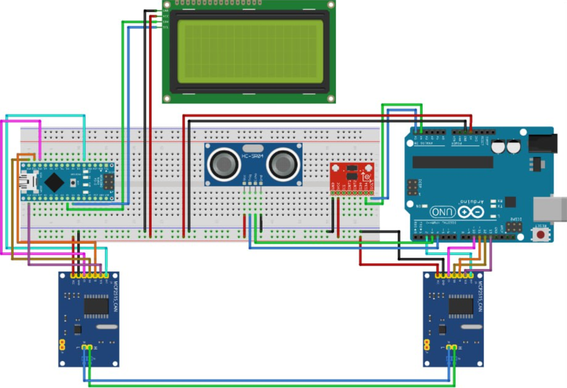
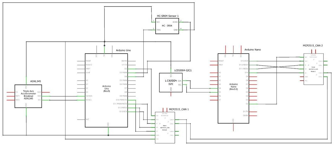
- Follow the circuit diagrams to connect the components.
- Module 1 (Sensor Data Transmission):
- Connect the ultrasonic sensor and ADXL345 to the Arduino.
- Connect the MCP2515 CAN module via SPI (CS pin to pin 10).
- Module 2 (Data Reception and Display):
- Connect the MCP2515 CAN module via SPI (CS pin to pin 10).
- Connect the 20x4 I2C LCD display to the Arduino.
-
Libraries
- Install the following Arduino libraries via the Library Manager or download from GitHub:
SPI.h: For SPI communication with the MCP2515 CAN controller.Wire.h: For I2C communication with the ADXL345 accelerometer and the LCD display.LiquidCrystal_I2C.h: For controlling the I2C LCD display.mcp2515.h(CAN bus library): For interacting with the MCP2515 CAN bus module.
- Install the following Arduino libraries via the Library Manager or download from GitHub:
-
Upload Code
- Module 1:
- Upload the Sensor Data Transmission code to the first Arduino.
- Module 2:
- Upload the Data Reception and Display code to the second Arduino.
- Module 1:
Program Modules
Module 1: Sensor Data Transmission
This module reads data from the ultrasonic sensor and the ADXL345 accelerometer. It packages this data into a CAN message and sends it via the MCP2515 CAN controller.
Module 2: Data Reception and Display
This module receives CAN messages sent by Module 1 and displays the sensor data on a 20x4 I2C LCD.
Graphical Connections
Breadboard Layout
Schematic Diagram
Wiring Connections
MCP2515 CAN Bus Module
| MCP2515 Pin | Arduino Pin |
|---|---|
| VCC | 5V |
| GND | GND |
| CS | D10 |
| SO | D12 |
| SI | D11 |
| SCK | D13 |
| INT | D2 |
I2C Device (e.g., 20x4 LCD)
| I2C Pin | Arduino Pin |
|---|---|
| VCC | 5V / 3.3 V |
| GND | GND |
| SDA | A4 |
| SCL | A5 |
Ultrasonic Sensor (HC-SR04)
| HC-SR04 Pin | Arduino Pin |
|---|---|
| VCC | 5V / 3.3 V |
| GND | GND |
| ECHO | D3 |
| TRIG | D4 |